Product Overview
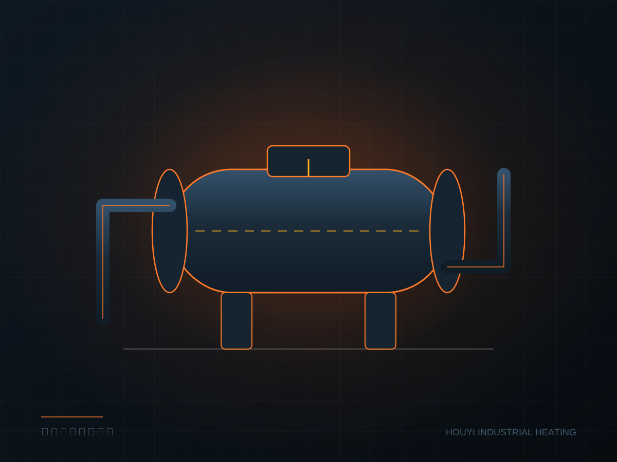
The HYF series welds a U-tube or straight-tube bundle to the flange, which bolts to the vessel opening and seals via a gasket. The elements extend into the medium from inside the vessel, transferring heat directly to the liquid without the temperature loss of a heat exchanger. Power is combined as needed from 3 kW to 500 kW; individual element power is generally kept under 9 kW to avoid excessive surface load and coking.
Bundle length, flange specification, and material are determined by actual vessel conditions. Standard sheaths are 304 or 316L; titanium or Incoloy 800 are selected for chloride-bearing media, while PTFE coating is common for strong alkali and high-purity water systems. Flanges can be machined to HG/T, ANSI B16.5, DIN, or JIS, with raised-face (RF), male-and-female (MFM), and tongue-and-groove (T/G) sealing faces.
The terminal box is fully isolated from the medium side; the cold end length keeps the gasket-area temperature below the gasket limit. For explosion protection, the terminal box is built to Exd IIB T4 or IIC T6 with a dedicated grounding terminal. The temperature probe mounts directly in the thermowell between bundle tubes, with the measuring point close to the heat zone—giving readings closer to the true liquid temperature than a probe on the vessel wall.
Construction Features
- Individual element power ≤9 kW with surface load kept under 4.5 W/cm² to reduce coking and carbon buildup
- Flange standards customizable to HG/T, ANSI, DIN, JIS, with raised-face and tongue-and-groove sealing
- Sheath options: 304, 316L, titanium, Incoloy 800, and PTFE coating
- Built-in thermowell accepts K-type or PT100 probes directly
- Explosion-proof terminal box Exd IIB T4 / IIC T6, protection class IP65
- Complete-bundle pull-out design—no need to drain the entire vessel for service
Technical Specifications
| Rated Power | 3 – 500 kW (grouped switching available) |
|---|---|
| Rated Voltage | 220V / 380V / 415V, 50/60Hz |
| Element Material | 304 / 316L / Titanium / Incoloy 800 / PTFE coated |
| Flange Standard | HG/T 20592, ANSI B16.5, DIN 2501, JIS B2220 |
| Flange Bore | DN80 – DN600 (3" – 24") |
| Working Pressure | ≤ 2.5 MPa (up to 6.4 MPa on request) |
| Max Temperature | 600°C (depends on medium and material) |
| Protection Class | IP65 / Explosion-proof Exd IIB T4, IIC T6 |
| Insulation Resistance | ≥ 100 MΩ (DC 500V, cold) |
The table lists typical configuration ranges. Special pressure, temperature or media conditions require re-checking; final parameters are confirmed by the approved drawings and technical agreement.
Typical Applications
- Reactor and tank heating
- Thermal-oil boiler auxiliary heating
- Large water and washing tanks
- Crude and heavy-fuel-oil tanks
- Boiler feedwater preheating
Information Needed for Selection
- Medium name, concentration, and whether it contains particles
- Total medium volume or circulation flow rate
- Initial and target temperature
- Required heat-up time
- Vessel or pipe size and material
- Supply voltage, phases, and available capacity
- Installation environment and hazardous-area requirements
- Connection standard and mounting orientation