Technical Article
Duct Heater Temperature Uneven? Check Cross-Section Air Velocity First
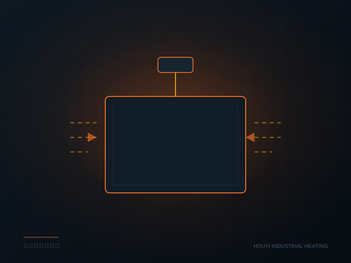
The heat source of a duct heater is the element surface, and the heat is carried away by airflow. Where air cannot reach, the element temperature runs away; where air moves too fast, outlet temperature is too low. So-called temperature unevenness is, in essence, uneven velocity distribution.
The reasonable range for cross-section velocity
Duct heaters are generally designed for 5–12 m/s. Below 5 m/s, the convective heat-transfer coefficient at the element surface is low, and surface temperature may exceed outlet temperature by more than 100°C, so fins easily collect dust and burn. Above 12 m/s, pressure loss and noise rise markedly and fan power increases.
Calculate it as airflow divided by duct cross-section. For 20,000 m³/h and a 1.2×0.8 m duct, velocity is 20000/3600/(1.2×0.8) ≈ 5.8 m/s — low but usable, compensated by longer elements or lower surface load.
Element layout determines cross-section uniformity
Elements must not be placed only in the middle of the duct. The right approach is uniform staggering across the section, with a 50–80 mm bypass gap at the edges to avoid wall-hugging airflow short-circuiting.
The number of layers matters too. A single layer has a small frontal area and high velocity but a short heat-transfer path; three staggered layers let the air fully turbulate, holding outlet ΔT within ±5°C. At the same power, more layers lower the surface load per element.
The upstream straight section is often ignored
If there is an elbow, reducer or fan outlet ahead of the duct heater, the air enters the heating section with a swirl, giving high flow on one side and low on the other. Standard practice is to keep 3–5 equivalent diameters of straight duct, or add a flow straightener ahead of the heater.
When a retrofit lacks space, a flow straightener is the quick, cheap fix: a perforated plate with 40%–50% open area, 200–300 mm ahead of the heater, cuts velocity deviation from 30% to within 10%.
How to arrange over-temperature protection
A single temperature point is not enough. Use at least three measurement points: outlet centre, outlet edge, and near the element surface. Measure element surface temperature with a sheathed thermocouple clamped to the tube wall, cutting power immediately above the setpoint.
The airflow switch must interlock with the fan. If the fan stops while the heater is still powered, the elements glow red within minutes — the most common cause of site accidents.
A common pitfall
Many projects size by "outlet temperature" yet ignore seasonal variation in inlet temperature. With an inlet of −5°C in winter and 35°C in summer, the same power gives a 40°C difference in outlet temperature. Size for the worst case, or fit SCR power control so output tracks inlet temperature automatically.
The duct heater structure itself is not complex; the hard part is matching it to the fan, duct and control system. Any mismatch in these three shows up as "uneven temperature" or "burned elements."